DATA  SHEET
Legacy ProductsFN5020
Sine Wave output filter for high-speed motor drives
20. Feb 2025
01. Jan 2015
Legacy Products
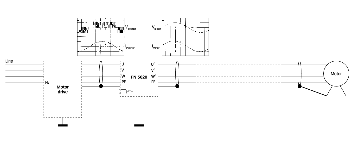
  • Smoothing of PWM drive output voltages
  • Increased service life of expensive high-speed motors
  • Reduction of audible motor noise
  • Improvement of system reliability
  • Production up-time for mission critical applications

Performance indicators

Technical Specifications
Maximum continuous operating voltage

3x500/288 VAC

Rated currents

25 to 120 A @ 50°C

DC link voltage

1000 VDC max.

Overload capability

1.5x rated current for 1 minute, once per hour

Residual ripple voltage

<5%

Motor frequency

0 to 600 Hz
0 to 600 Hz

Motor cable length

200 m max.

Switching frequency

6 to 15 kHz
6 to 15 15

High potential test voltage

P –> E 2000 VAC for 2 sec
P –> P 1000 VDC for 2 sec

Temperature range (operation and storage)

-25°C to +100°C (25/100/21)

Protection category

IP 20

Flammability corresponding to

UL 94 V-0

Design corresponding to

UL 1283, CSA 22.2 No. 8 1986

Lifetime (calculated)

>10 years (25, 55 A)
~5 years (75, 120 A)

Approvals & Compliances

Features and Benefits

  • Suitable for fast rotating fields up to 600 Hz
  • Conversion of the PWM output signal (symmetrical voltage components) of motor drives into a smooth sine wave with low residual ripple
  • Elimination of premature motor damage caused by high dv/dt, overvoltages, motor overheating and eddy current losses
  • Significantly increased service life of expensive (high-speed) motors
  • Reduction of the pulse load of motor drive IGBTs and the parasitic losses on long shielded motor cables
  • Less interference propagation towards neighboring equipment or lines
  • Advanced choke design to minimize filter losses and voltage drop
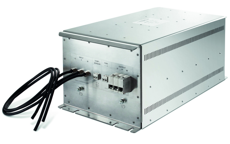
  • IP 20 protection, touch-safe terminals and temperature monitoring function to increase overall equipment safety

Typical Applications

Motor drives and motors in high-speed applications, like:


  • High-speed spindles
  • Textile machinery
  • Lasers
  • Military appliances (400 Hz)

Motor drive applications with medium to long motor cables and/or with multiple motors in parallel, like:


  • Pumps
  • Conveyors

Typical electrical schematic

Filter selection table

Filter 

Rated current 

Typical motor 

Typical 

Output 

Weight 


@ 50ºC 

power rating* 

power loss** 

connections 


[A] 

[kW] 

[W] 

[kg]

FN 5020-25-33 

25 

15 

n.a. 

-33 

13

FN 5020-55-34 

55 

30 

n.a. 

-34 

29

FN 5020-75-35 

75 

45 

n.a. 

-35 

49

FN 5020-120-35 

120 

75 

n.a. 

-35 

57

Typical block schematic

Temperature monitoring function

All filters of this range are equipped with a temperature monitoring function. The built- in temperature sensor opens a potential-free contact in the case of filter overtemperature (>120ºC). The maximum switching capability is 6 A/250 V. This function can be used, for example, in the input of a CNC controller or as the trip of a circuit breaker in order to interrupt the mains power supply. Connections are located next to the phase connectors (see mechanical data for details).

Forced cooling

The 75 A and 120 A filters provide internal cooling fans which require external power supply (24 VDC/~4 W). Connections are located next to the connectors of the temperature sensor (see mechanical data for details).

For additional information please consult the Schaffner application note „Sinus Plus − New Output Filter Concept for Power Drive Systems“.

Mechanical data

25 and 55 A types

75 and 120 A types

Dimensions


25 A 

55 A 

75 A 

120 A

410 

554 

799 

799 

200 

250 

343 

343 

163 

203 

280 

280 

350 

500 

725 

725 

380 

524 

760 

760 

F1 

120 

170 

172 

172 

F2     

296 

296 

6.5 

25 

39 

45 

45 

M6 

M6 

M8 

M8 

K1 

60 

70 

88 

88 

K2 

55 

55 

70 

70 

50 

69 

80 

80 

AWG 10 

AWG 6 

25mm2

35mm2

1000 +20/-0 

1000 +20/-0 

1000 +20/-0 

1000 +20/-0 

20 

20 

20 

20 

Filter output connector cross sections

-29 

-33 

-34 

-35

Solid wire 

6 mm2

16 mm2

35 mm2

50 mm2

Flex wire 

4 mm2

10 mm2

25 mm2

50 mm2

AWG type wire 

AWG 10 

AWG 6 

AWG 2 

AWG 1/0

Recommended torque 

0.6-0.8 Nm 

1.5-1.8 Nm 

4.0-4.5 Nm 

7-8 Nm

Headquarters, Global Innovation and Development

Switzerland
Schaffner Group
Industrie Nord
Nordstrasse 5
4542
Luterbach
+41 32 681 66 26
info@schaffner.com

To find your local partner within Schaffner‘s global network schaffner.com

© 2025 Schaffner Group

The content of this document has been carefully checked and understood. However, neither Schaffner nor its subsidiaries assume any liability whatsoever for any errors or inaccuracies of this document and the consequences thereof. Published specifica-tionsw are subject to change without notice. Product suitability for any area of application must ultimately be determined by the customer. In all cases, products must never be operated outside their published specifications. Schaffner does not guarantee the availability of all published products. This disclaimer shall be governed by substantive Swiss law and resulting disputes shall be settled by the courts at the place of business of Schaffner Holding AG. Latest publications and a complete disclaimer can be downloa-ded from the Schaffner website. All trademarks recognized.


Sales and Application Centers

Switzerland
Schaffner EMV AG
Industrie Nord
Nordstrasse 5
4542
Luterbach
+41 32 681 66 26
switzerlandsales@schaffner.com

Singapore
Schaffner EMC Pte Ltd.
Blk 3015A Ubi Road 1 #05-09 Kampong Ubi Industrial Estate
408705
Singapore
+65 63773283
singaporesales@schaffner.com