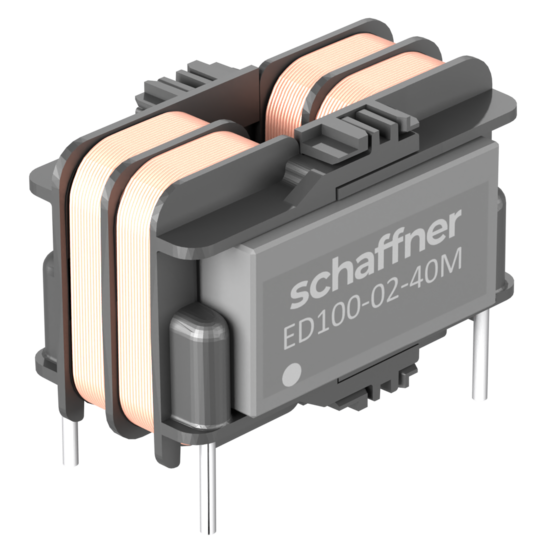
Lighting LED drivers need to be high in efficiency, low in cost and compliant to EMC regulations. The ED100 / ED101 series increases the efficiency of a LED driver circuit by reducing the need for X-capacitors. Thus, the power factor rises, and less unwanted reactive power is generated. The inductor is a combination of a strong common-mode inductance with a significant differential-mode inductance. It offers two filtering elements in one component. This helps the circuit designer to reduce the number of elements on the PCB, to reduce space requirement as well as lowering costs. Combined with the high MTBF value of the ED100 / ED101 series, a circuit design with reduced number of components profits for its overall reliability and lifetime.
Stromkompensierte Drosselreihe für Beleuchtungsanwendungen
Articles
| Article | Rated Current @ambient | Inductance | Input/Output connections (Nm) | Distribution stock | Compare | Read More | |
|---|---|---|---|---|---|---|---|
| L1 | Input terminal | ||||||
 | ED100-0.2-40M | 0.2 | 40 | PCB Pin | |||
 | ED100-0.3-27M | 0.3 | 27 | PCB Pin | |||
 | ED100-0.4-20M | 0.4 | 20 | PCB Pin | |||
 | ED100-0.5-15M | 0.5 | 15 | PCB Pin | |||
 | ED100-0.75-12M | 0.75 | 12 | PCB Pin | |||
 | ED100-1-9M0 | 1 | 9 | PCB Pin | |||
 | ED100-1.25-7M0 | 1.25 | 7 | PCB Pin | |||
 | ED100-1.5-5M0 | 1.5 | 5 | PCB Pin | |||
 | ED100-2-3M0 | 2 | 3 | PCB Pin | |||
 | ED101-0.2-40M | 0.2 | 40 | PCB Pin | |||
 | ED101-0.3-27M | 0.3 | 27 | PCB Pin | |||
 | ED101-0.4-20M | 0.4 | 20 | PCB Pin | |||
 | ED101-0.5-15M | 0.5 | 15 | PCB Pin | |||
 | ED101-0.75-12M | 0.75 | 12 | PCB Pin | |||
 | ED101-1-9M0 | 1 | 9 | PCB Pin | |||
 | ED101-1.25-7M0 | 1.25 | 7 | PCB Pin | |||
 | ED101-1.5-5M0 | 1.5 | 5 | PCB Pin | |||
 | ED101-2-3M0 | 2 | 3 | PCB Pin |
Funktionen und Vorteile
Typische Anwendungen
Technische Spezifikationen
Nennströme
0.2 to 2 A @ 65°C
Arbeitsfrequenz
DC to 60 Hz
Luft- und Kriechstrecken
Creepage > 3 mm / Clearance > 2.5 mm between windings
Nenninduktivität
3 to 40 mH common-mode
Betriebsspannung
300 VAC, 50/60 Hz
Überspannungskategorie
II acc. IEC 60664-1
Verschmutzungsgrad
PD2 acc. IEC 60664-1
Streuinduktivität
0.1 - 3.1 mH
Induktivitätsreduzierung (DC-Bias mit IN)
Less than 10% at rated current
Temperaturbereich (Betrieb und Lagerung)
-40°C to 125°C
Klimaklasse
40/125/56 acc. IEC 60068-1
Kühlung
AN - natural convection
Höhe
Derating above 2,000 m
Schutzart
IP 00
Entflammbarkeit entsprechend
UL 94 V-0
Vibration und Schock
3M4 acc. IEC 60721-3-3
Design entsprechend
IEC 60938-1/-2
MTBF (Mil-HB-217F)
>13,000,000 h @ 65°C/250 V


